
The term “30-008 Colibri pinout” may not be instantly familiar to the average user, but in specialized electronic and embedded systems communities, this keyword signifies a crucial technical reference point. Whether you’re an engineer dealing with embedded systems, a technician working with Colibri computing modules, or a student trying to understand digital communication interfaces, the 30-008 Colibri pinout can serve as a foundational guide to interfacing and hardware configuration.
In this comprehensive article, we will explore all angles of the 30-008 Colibri pinout, including its structure, function, uses in embedded computing, electrical layout, and frequently asked questions to remove ambiguity. The aim is to leave no technical stone unturned while keeping our core focus keyword intact: 30-008 Colibri pinout.
Introduction to the 30-008 Colibri Pinout
To begin with, the 30-008 Colibri pinout refers to the specific electrical and logical mapping of pins for a Colibri module, most likely in the Toradex Colibri family of System on Modules (SoMs). The designation “30-008” may represent a part number or a variant of Colibri modules used in embedded applications such as IoT devices, industrial control panels, automotive systems, or medical instrumentation.
A pinout itself is the arrangement or mapping of pins for a connector or interface, showing what each pin does — power, ground, signal, or function-specific. Thus, the 30-008 Colibri pinout helps you understand how to physically and logically connect a module to the rest of your electronic system.
Hardware Overview of Colibri Modules
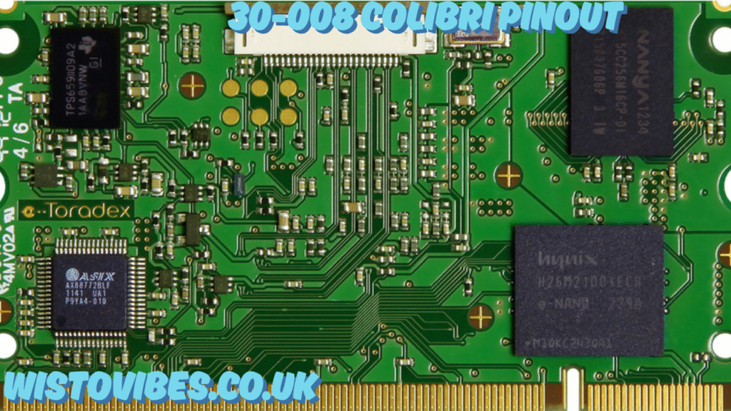
Before diving into the specifics of the 30-008 Colibri pinout, let’s understand what a Colibri module is. Colibri is a family of compact, low-power computer-on-modules (COMs) from companies like Toradex. These modules typically feature ARM-based processors and are used in embedded computing systems.
Each module is equipped with two main connector interfaces — typically a SODIMM (Small Outline Dual Inline Memory Module) connector, which houses multiple pins. These connectors include power supply lines, data buses (I2C, SPI, UART), GPIOs (General Purpose Input/Output), display signals, and peripheral interfaces like USB, CAN, and more.
The 30-008 Colibri pinout gives the precise configuration for one of these Colibri variants, defining which pins on the connector correspond to what function.
Deep Dive: Understanding the 30-008 Colibri Pinout
The 30-008 Colibri pinout can be broken down into several categories based on signal types and interface functions:
1. Power Supply Pins
Power pins in the 30-008 Colibri pinout include multiple voltage inputs such as:
- 3.3V or 5V inputs
- GND (ground) pins
- Voltage outputs for sensors or other peripheral components
These ensure the module is powered correctly and capable of delivering supply to low-power external components.
2. Data Communication Pins
Several data communication protocols are defined in the 30-008 Colibri pinout, including:
- UART (Universal Asynchronous Receiver/Transmitter): Used for serial communication. Common pins include TXD, RXD, CTS, and RTS.
- I2C (Inter-Integrated Circuit): Pins labeled SCL (clock) and SDA (data) used for low-speed peripheral communication.
- SPI (Serial Peripheral Interface): Includes MISO, MOSI, SCK, and Chip Select pins for high-speed synchronous communication.
3. General Purpose Input/Output (GPIO)
GPIO pins on the 30-008 Colibri pinout are highly flexible and programmable. They may serve different roles such as:
- Digital I/O
- PWM (Pulse Width Modulation)
- Interrupt request lines
- Control lines for LEDs, buzzers, or relays
Each GPIO pin will usually be labeled with a number or identifier, often mapped through the system’s firmware.
4. Multimedia and Display Interfaces
If your system uses graphical output or camera input, the 30-008 Colibri pinout may include:
- RGB display signals
- LVDS (Low Voltage Differential Signaling)
- Touchscreen interface signals
- Camera Serial Interface (CSI) signals
These are often used in HMI (Human Machine Interface) systems in industrial panels or kiosks.
5. USB and Networking
Some modules using the 30-008 Colibri pinout have USB Host and OTG support, with dedicated pins for:
- USB D+ and D-
- Ethernet signals (TX, RX pairs)
- CAN interface for automotive and industrial networking
These enable both data transfer and peripheral integration for advanced embedded designs.
How to Read and Apply the 30-008 Colibri Pinout
Reading the 30-008 Colibri pinout effectively involves:
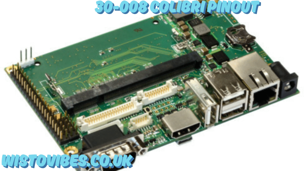
- Consulting the SODIMM layout chart, typically showing pin numbers on each side.
- Using signal definitions to identify where power, data, and ground signals are routed.
- Cross-referencing with your carrier board schematic to ensure compatibility.
- Matching voltage levels and tolerances to avoid damaging the module.
It is crucial to handle the board using anti-static procedures and always check voltage requirements before powering it up.
Practical Use Cases for 30-008 Colibri Pinout
The 30-008 Colibri pinout plays a key role in various embedded projects:
Industrial Automation
- Connect sensors via GPIOs and analog inputs
- Control actuators using PWM or GPIO outputs
- Interface with industrial buses using CAN or UART
Medical Devices
- Integrate with touch displays and control panels
- Communicate with diagnostic peripherals via I2C or USB
Automotive Systems
- Use CAN bus and GPS interfaces
- Connect camera modules and displays
IoT Gateways
- Use WiFi or cellular modules through UART or USB interfaces
- Route signals through GPIOs for monitoring or remote triggering
Tips for Troubleshooting 30-008 Colibri Pinout Issues
Working with embedded hardware always carries a risk of signal misrouting or voltage mismatches. When dealing with the 30-008 Colibri pinout, consider these tips:
- Always measure voltage levels before connecting sensitive components.
- Use a continuity tester or multimeter to verify pin-to-function mapping.
- Update firmware or bootloader to match hardware pin configurations if programmable.
- Avoid short circuits by ensuring proper grounding and insulation between adjacent pins.
- Refer to datasheets or hardware manuals for accurate mapping of pin functions.
Frequently Asked Questions (FAQs)
Q1: What does “30-008” signify in the 30-008 Colibri pinout?
A1: “30-008” likely refers to a part number or specific module identifier within the Colibri family. It distinguishes a particular configuration or hardware version.
Q2: Can I use a different Colibri module with the same pinout?
A2: Not always. While many Colibri modules maintain pin compatibility, variations in processor architecture or features might affect pin function. Always consult the module’s datasheet.
Q3: How many GPIOs are available in the 30-008 Colibri pinout?
A3: Depending on the configuration, there can be dozens of GPIO pins, each capable of different roles such as digital I/O, PWM, or interrupts.
Q4: Are the pin functions fixed or programmable?
A4: Many pins in the 30-008 Colibri pinout are multiplexed, meaning they can be configured for different functions (e.g., UART vs GPIO) using software.
Q5: What tools are needed to work with the 30-008 Colibri pinout?
A5: You’ll need access to the module’s carrier board, multimeter, logic analyzer (optional), and embedded development tools like a debugger or IDE.
Conclusion: Why the 30-008 Colibri Pinout Matters
Understanding the 30-008 Colibri pinout is essential for designing robust and efficient embedded systems. Whether you’re building an industrial control system, a smart medical interface, or a custom IoT solution, correct pin mapping ensures stability, safety, and performance. The pinout serves as the bridge between the computing core and the real world — and misinterpretation can lead to failure or damage.
Also read : 2330 W Glenrosa Av Apt 223 Ph A 85015: What to Know About This Phoenix Address??